Building a Roll-Off Roof Observatory: Pier Design, Layout, and Automation in Bortle 8
9 Jan 2026
The Breaking Point: From Portable to Permanent
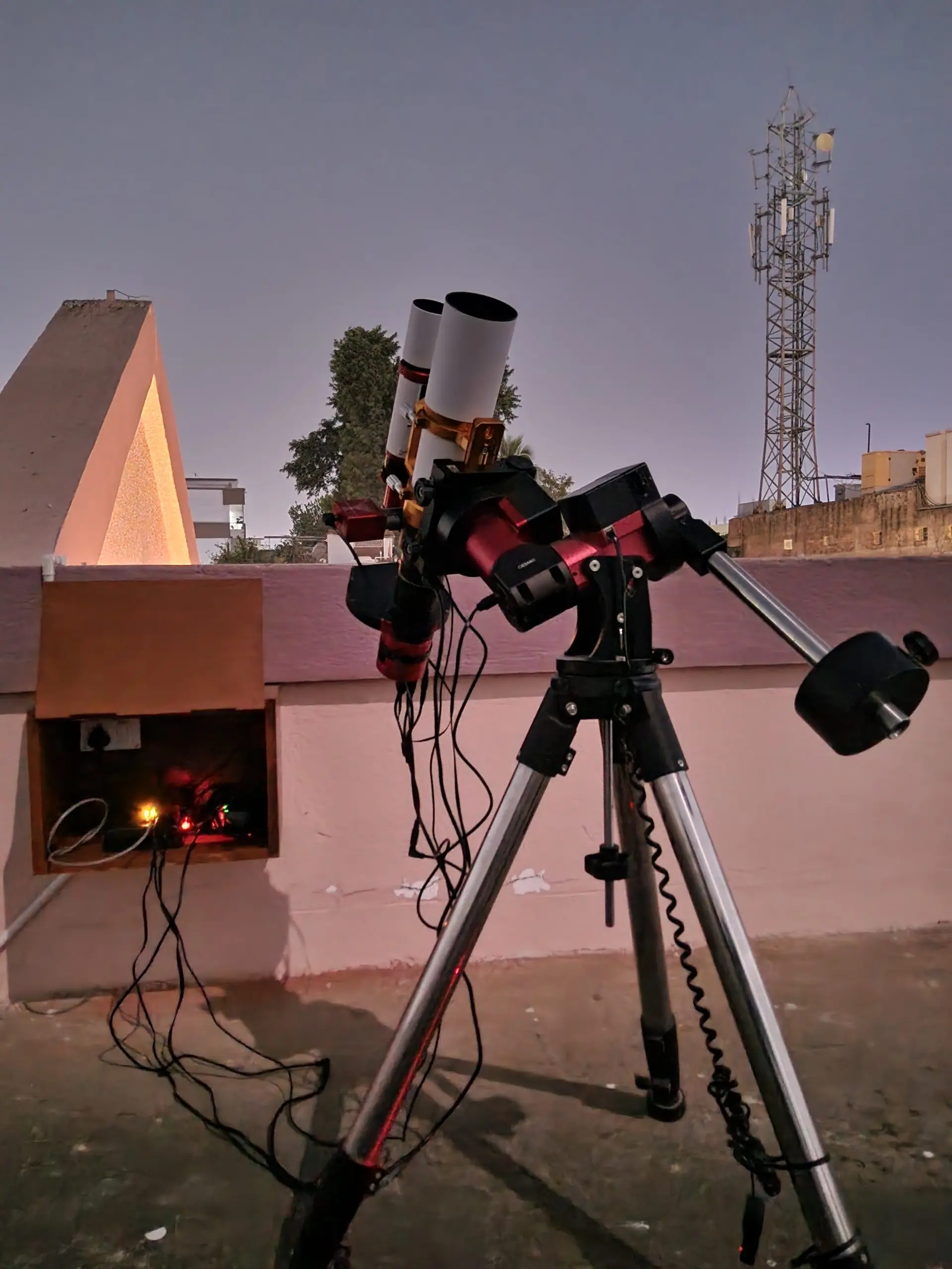
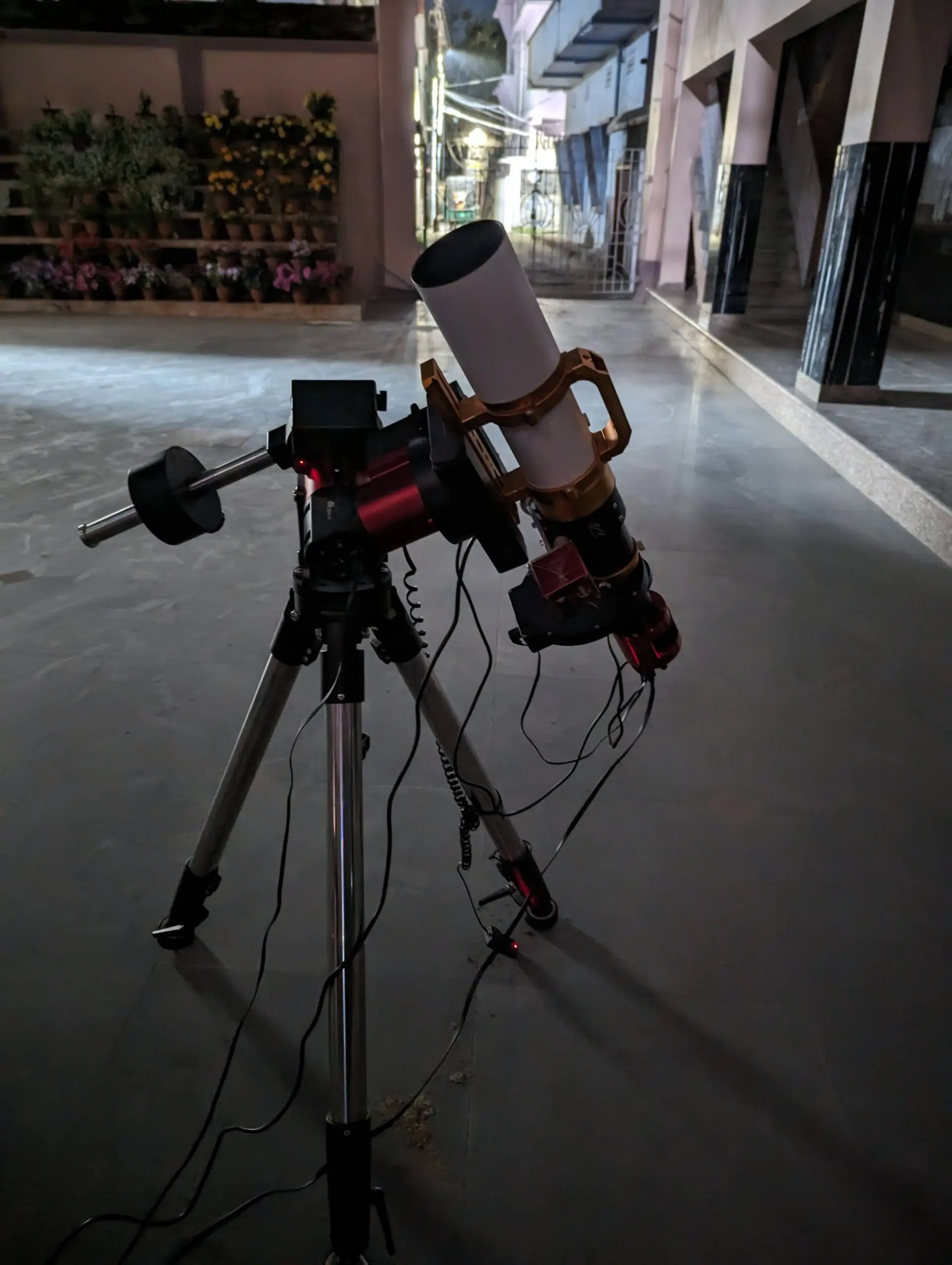
This observatory did not begin as a building project. It began on a rooftop with a portable imaging rig that was assembled and dismantled around workdays, weather windows, and fatigue.
That phase mattered. It forced discipline regarding alignment, focus, guiding, and failure when nothing was permanent and everything had to be rebuilt each night. It also exposed a hard limit. Beyond a certain point, portability stops being freedom and starts becoming friction.
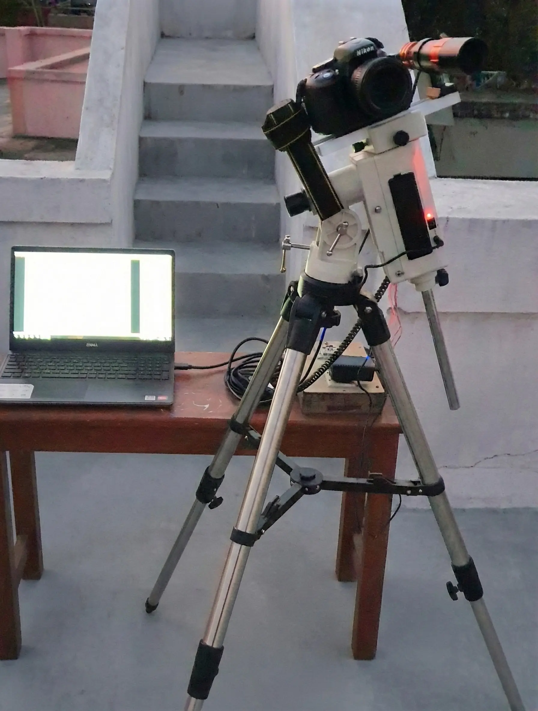
My learning curve evolved around an iOptron CEM40 and a William Optics 71GT APO imaging from a rooftop. Over time, the setup grew to include an Optolong L-eXtreme filter, a ZWO filter wheel, guiding, and an ASIAIR. For this scale and focal length, assembly was predictable and the abstraction the ASIAIR provided was an advantage.
As the equipment evolved and focal lengths grew, the bottleneck was no longer learning or ambition. It was time. Clear skies do not wait for setup, and long nights do not coexist easily with professional schedules.
That balance shifted permanently when I decided to move to longer focal lengths. After evaluating multiple optical paths, I settled on a Celestron C8 EdgeHD. It offered the reach I wanted without pushing complexity too far into unfamiliar directions. Along with the C8, I added a ZWO ASI2600MM Pro and a full suite of RGB and SHO filters.
At this point, the constraints became strictly physical. Carrying a C8 and its associated accessories across two floors, repeatedly and reliably, was not sustainable. Setting up and tearing down equipment at the end of long consulting days started to feel like a liability. The idea of permanence did not arrive as an upgrade. It arrived as a way to stay honest about what was realistically possible, transforming the observatory from an abstract idea into a practical necessity.
Spatial Engineering: The 18x10 Footprint
With the C8 already in hand and one mount pending arrival, I shifted focus to the physical layout. This phase involved studying mount and telescope dimensions, measuring the equipment, and mapping out slew envelopes on paper and on the floor.
The primary problem to solve was fixing spatial constraints before pouring concrete removed my ability to change them. Given the cost, complexity, and permanence of the build, I made a deliberate constraint. The observatory would support exactly two piers, with zero scope for future expansion. This was not a compromise. It was a clarity decision. The entire structure was designed around this fact rather than leaving half-implemented flexibility that would likely never be used.
I started this phase by creating a rough drawing with high-level dimensions, handing it over to the contractor responsible for the civil structure. For the roll-off roof, I engaged a local fabricator and shared reference designs. Roll-off roof observatories are uncommon here, and his lack of prior experience was evident. That was a risk I accepted deliberately. To compensate, I provided explicit guidelines, measurements, and constraints around roof travel, locking, and wind resistance. This required far more involvement than a conventional structure, but it ensured the original intent was preserved during execution.


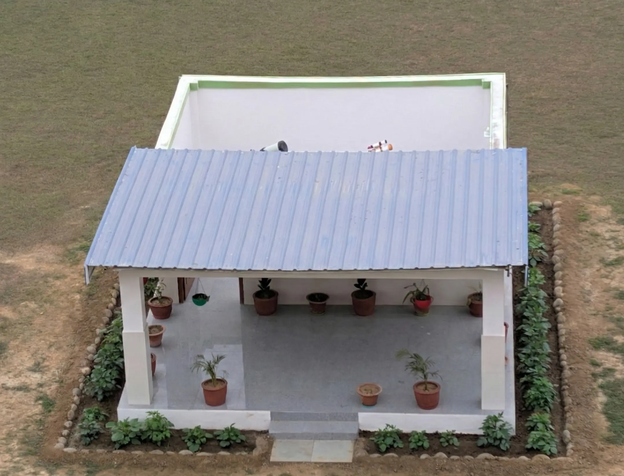
The internal observatory space measures 18 feet by 10 feet. This size was chosen to ensure safe clearance during slews, comfortable access around both setups, and zero interference between the two mounts.
The layout details are highly specific. On the short 10-foot side, each pier sits exactly 5 feet away from the walls. On the long 18-foot side, the layout divides into 5 feet from the wall to the first pier, 6 feet between the two piers, and 5 feet from the second pier to the opposite wall. The roof rolls off along the 10-foot side, extending another 10 feet when open. When fully opened, the effective footprint becomes roughly 18 by 20 feet. The entire structure is concrete, built on a full foundation for long-term stability.
Mechanical Grounding: Dual-Plate Pier Design
The next problem to solve involved establishing the foundation. I had to determine how low the piers could be while still preserving usable sky, maintaining mount clearance, and ensuring long-term flexibility. Each granite tiled pier was dug seven feet deep into the ground and sized at nine by nine inches. While both concrete foundations are identical, the pier tops had to be entirely different, driven by the specific mounts they support.
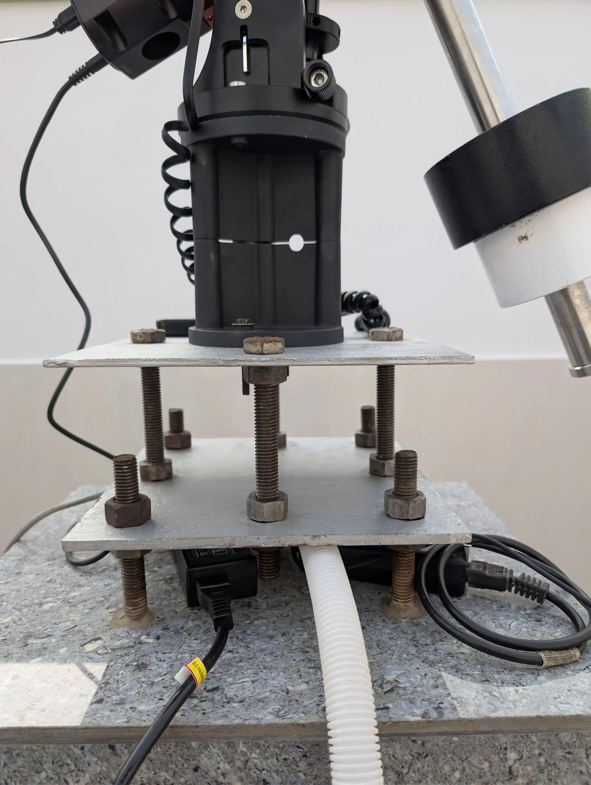
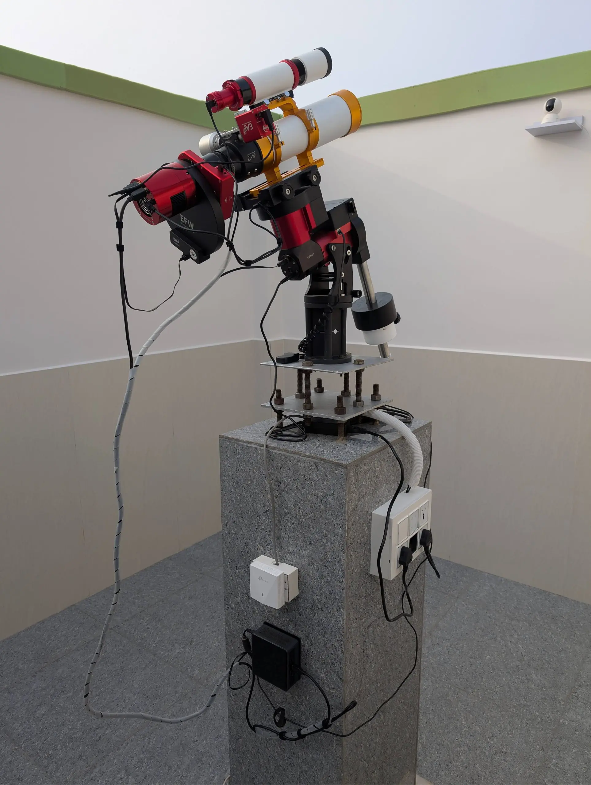
I chose a bolted, plate-based pier-top design rather than a fixed adapter. This approach provides mechanical rigidity while still allowing fine alignment and future serviceability. The construction relies on four long anchor bolts embedded directly into the concrete pier. A bottom steel plate is secured using nuts above and below the plate. A second set of four bolts rises from this foundation plate to support the top steel plate, where the mount is finally installed. This creates a highly rigid sandwich structure while permitting controlled, millimeter-level height and leveling adjustments.
The two mounts required different top plate dimensions. The iOptron CEM70 required an 11-by-11 inch plate, while the CEM40 needed a 9-by-9 inch plate. Both bottom plates were fabricated using 8mm steel, and the top plates were initially cut from 8mm steel as well. This worked flawlessly for the CEM40. However, during the installation of the CEM70, I discovered that its mounting screws were too short to pass through the thick 8mm plate and engage securely. Rather than modifying the expensive mount hardware, I replaced the CEM70 top plate with a 4mm thick steel plate. Since the plate had to be removed anyway, I used the opportunity to correct the mechanical polar alignment angle, which was slightly off from true north.
The true value of the two-plate pier design became apparent during the final equipment mounting phase. Because the vertical spacing between the bottom and top plates is adjustable, I was able to fine-tune the effective pier height after the fact. When I installed the Celestron C8 EdgeHD with its extended accessories to meet back-focus requirements, the filter wheel began to foul the pier at extreme positions. Instead of redesigning the hardware or limiting slews, I simply increased the seated height of the C8 by raising the nuts between the plates.
For the wide-field setup, I encountered the opposite problem. The total height of the CEM40 and WO 71GT APO system was insufficient, and the telescope was not clearing the observatory wall when parked at the home position. I already owned an iOptron tri-pier and decided to repurpose its core extension here. The arc-shaped azimuth adjustment slots on the CEM40 made it relatively forgiving to install on this mini-pier, as small orientation errors could be corrected easily during polar alignment. The mini-pier provided the exact additional height needed to clear the walls safely.
In hindsight, these adjustments reinforced the value of designing for post-installation flexibility. Problems that would otherwise have required structural changes were solved with simple mechanical tuning instead.
The Gear Roster: Wide-Field and Deep Space Operations
With the foundation poured and the plates leveled, the observatory was ready to receive its permanent payloads. The dual-pier layout was specifically designed to handle two entirely distinct imaging regimes simultaneously without the physical interference that plagues temporary setups.

The first pier is dedicated to wide-field framing. It houses the William Optics 71GT APO paired with a 6AIII reducer, all sitting on the iOptron CEM40 mount. I paired this optical tube with the monochrome ZWO ASI2600MM Pro and a 7-position filter wheel to handle full narrowband and broadband projects. Guiding is managed by a 50mm guidescope and an ASI120MM camera. This system is a known quantity, requiring minimal intervention once a sequence begins.
- Telescope
- William Optics 71GT APO (6AIII Reducer)
- Mount
- iOptron CEM40
- Camera
- ZWO ASI2600MM Pro (Mono)
- Filters
- 7-Position ZWO EFW
- Guiding
- WO 50mm Guidescope + ASI120MM

The second pier is built for reach and flexibility. It carries the Celestron C8 EdgeHD mounted on the heavier iOptron CEM70 WiFi. For deep space imaging, I use a 0.7x reducer and the color ZWO ASI294MC Pro, backed by a 5-position filter wheel. Because this optical train demands a much higher degree of precision, I integrated a Celestron Off-Axis Guider with the highly sensitive ASI220MM guide camera to fight flexure.
Having a permanent setup also affords the luxury of easily swapping imaging trains based on the target or conditions. While the ASI294MC Pro handles deep sky duties, I also own a ZWO ASI676MC. This camera will be rotated in for high-resolution planetary and lunar imaging, utilizing the C8 EdgeHD at its native focal length without the reducer.
- Telescope
- Celestron C8 EdgeHD
- Mount
- iOptron CEM70 WiFi
- Deep_Sky_Camera
- ZWO ASI294MC Pro (Color)
- Planetary_Camera
- ZWO ASI676MC (Color)
- Guiding
- Celestron OAG + ASI220MM
Environmental Control, Telemetry, and IoT Automation
Environmental conditions were a major design input for the structure. Summer temperatures routinely reach 48°C, while winter lows drop to 3°C and are often accompanied by heavy fog and haze. The monsoon season also lasts nearly four months, bringing sustained humidity and rain. To mitigate these extremes, the roof uses a two-layer construction consisting of an outer layer of fiber plastic and an inner layer of compressed wood board. This was done intentionally to reduce heat buildup. A single-layer roof would have turned the observatory into an oven during peak summer months. The roll-off design also provides an immediate benefit for imaging, as the observatory equalizes quickly with ambient conditions once opened, avoiding trapped warm air and internal turbulence.
The interior philosophy was strict. The space contains nothing except the equipment. There are no storage cabinets, workbenches, or visual distractions. Dust protection, however, required careful thought. I explored off-the-shelf dust-proofing options and evaluated bristled sealing strips, but they were prohibitively expensive. I opted for a simpler, more controllable solution instead. A wooden strip was installed along the inner walls, and foam was attached to these strips. When the roof is closed, it lightly touches the foam to seal the gap. It is not airtight, but it significantly reduces dust ingress without introducing friction or mechanical complexity.
I intentionally avoided complex concealed wiring for power and networking. Each pier has its own dedicated switchboard containing four power sockets planned for the mount, camera, NUC, and a spare. All sockets are connected to IoT-controlled switches.


I access these through a mobile app, allowing me to independently power on or shut down individual components without being physically present. This setup has proven incredibly useful. Power-cycling a misbehaving device remotely often resolves issues that would otherwise require a site visit in the middle of the night.
For the control computers, I configured the NUC BIOS to automatically power on when power is restored. This ensures that after any planned or unplanned power interruption, the systems come back online without manual intervention. Networking is handled by a PoE-powered Wi-Fi access point, keeping cabling minimal while providing stable connectivity across the 18x10 footprint. Given my consulting schedule and frequent travel, reliable remote access was an absolute requirement. I rely on Tailscale installed on a Synology NAS, the image processing PC, and both observatory NUCs. Once connected via VPN, I primarily use Windows Remote Desktop to access the observatory, keeping AnyDesk and TeamViewer installed as redundant backups.
The Software Shift: Leaving ASIAIR for NINA
In parallel with the physical build, I transitioned the control software from ASIAIR to NINA. This was a non-trivial shift. ASIAIR had trained me to operate within guided workflows with minimal parameter exposure. However, scaling up to the Celestron C8 brought new constraints. Long focal lengths, tight focus tolerances, massive file sizes, and zero tolerance for unreliable recovery during unattended imaging runs required a new approach. NINA exposes all of these underlying mechanics and expects you to understand what you are doing.
With the CEM40 and William Optics 71GT setup, I had reached a point where alignment and imaging could be initiated in roughly thirty minutes. Even after moving to NINA, this efficiency remained largely intact. The Celestron C8 introduced an entirely different class of challenges. Focusing alone was an eye-opener. Typical ZWO EAF positions with the refractor sat in the 5,000 to 6,000 step range. With the C8, focus positions extended outward to 195,000 steps. This forced me to actively engage with parameters that were effectively invisible in the ASIAIR environment, including step size calculation, backlash compensation, and autofocus curve strategy.
At the time of writing, I am still tuning the fully automated NINA sequences for the C8. The primary learning curve currently centers around autofocus behavior, sequencing logic, and building confidence in meridian flips and automated recovery routines. The system demands respect. Whether this upfront effort pays off long-term remains to be seen, but the direction is clear.
Closing Thoughts on the Build
This observatory was built around constraints and aspirations. The constraints were non-negotiable. I had limited personal time, unpredictable weather windows, and seeing conditions that reward readiness rather than effort. The aspirations were equally clear. I wanted to gain the freedom to image within those limits and push into longer focal lengths without turning every session into a logistical exercise. Every decision documented here reflects that balance.
The structure is fully operational. The roof remains manual, the transition to NINA is ongoing, and the early groundwork for planetary imaging is just beginning. As providence always dictates, it is currently winter, foggy, and the skies are rarely clear.
The structure is finished. The learning is not. That is exactly how it should be.